Adaptive Mould Components
The robotic Adaptive Mould solution is divided into two main technology areas.
Moulding components
That shape the surface to be used for formwork.
Steering components
For accurate 3D positioning of the mould surface
Protective silicone sheet
On top of the membrane a thin silicone sheet is placed, and may be held in place by vacuum, to reduce tear and wear of the membrane and to secure the most optimal and correct surface depending on the panel material and surface demand.
3D laser
The casting sides can easily be placed using a 3D laser placed 3-5 meters above the adaptive mould. The laser also laser-guides correct placement of panels, ornaments, letters or alike to be placed on the casting surface.
Silicon ferromagnetic composite membrane
A heavy 18 mm thick silicon ferromagnetic composite membrane serves as the initial mould surface. This part of the membrane either consist of glue-joined tiles that are practical and easy to distribute, handle and replace, or a full size casted membrane.
Control unit
The 3D designs are transferred to the mould from the control unit, which acts as the central nervous system that manages mould operations and configurations.
Membrane Supporting Magnets
Topping the rod system membrane supporting magnets are placed, to hold the membrane in place as the adaptive mould is moving into the desired curvature.
Software
Our own software Adapa Tools, is a Rhino plugin software that prepares the CAD files for the panel prior to fabrication. The software analyses and optimizes the design of each panel in accordance with the specific mould that is being used. The software supports files formats such as 3dm, iges, stl, stp, 3ds, dwg, etc.
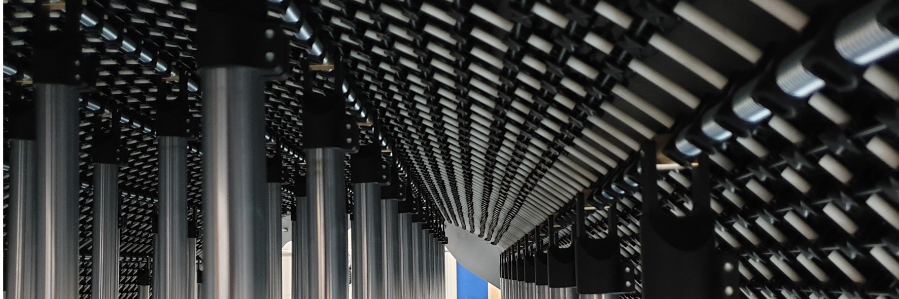
Flexible rod system
A system of mould type specific rods positioned by the fork joints and interconnected between rows and lines, is essential for accuracy and low tolerance in the final casting surface position.
Electrical Stepper Motors
Adapa designed Electrical Stepper Motors turn the adaptive mould into position. The motors are controlled by the Computer Aided Manufacturing (CAM) software in the Control Unit that communicate with PCB’s placed in each individual stepper motor.
Casting sides and magnetic shuttering
On top of the adaptive mould casting sides of different types and styles can be used. Due to the magnetic properties of the membrane, custom magnetic shuttering systems can be used.
Linear actuators
Linear actuators are powered by the stepper motors to bring the fork joints positioned at the top of each actuator, into the exact 3D position determined by the 3D shape in the Adapa Tools software.
Adaptive Moulds specified to your needs in four simple steps